
Description:
This project uses a keyboard to move a robot around. We will use the video series starting with “Raspberry Pi Devastator Robot # 1,” by Youtube channel Explaining Computers, which details various topics such as putting together the parts in the base kit, configuring autoload on boot, importing libraries for motor control, wiring, batteries, etc…
The Devastator Kit comes with a set of great motors so you only need to provide a pi, a motor controller, some batteries, an internet connection, and some wires. It helps to also have an HDMI connection to a screen. You can use any Raspberry Pi. The tutorial below uses a Pi Zero which fits much better than the Pi 3 that we use. This means we will have to engineer a way to make it all fit together without sacrificing functionality.
Supply links
Devastator Kit ($74) https://amzn.to/2Je3cbx.
Raspberry Pi ($40) https://amzn.to/3exiBPX.
L298N Motor Controllers ($10) https://amzn.to/2I9fMsi
Wires ($11) https://amzn.to/3ewVMMl
The starting video can be found below:
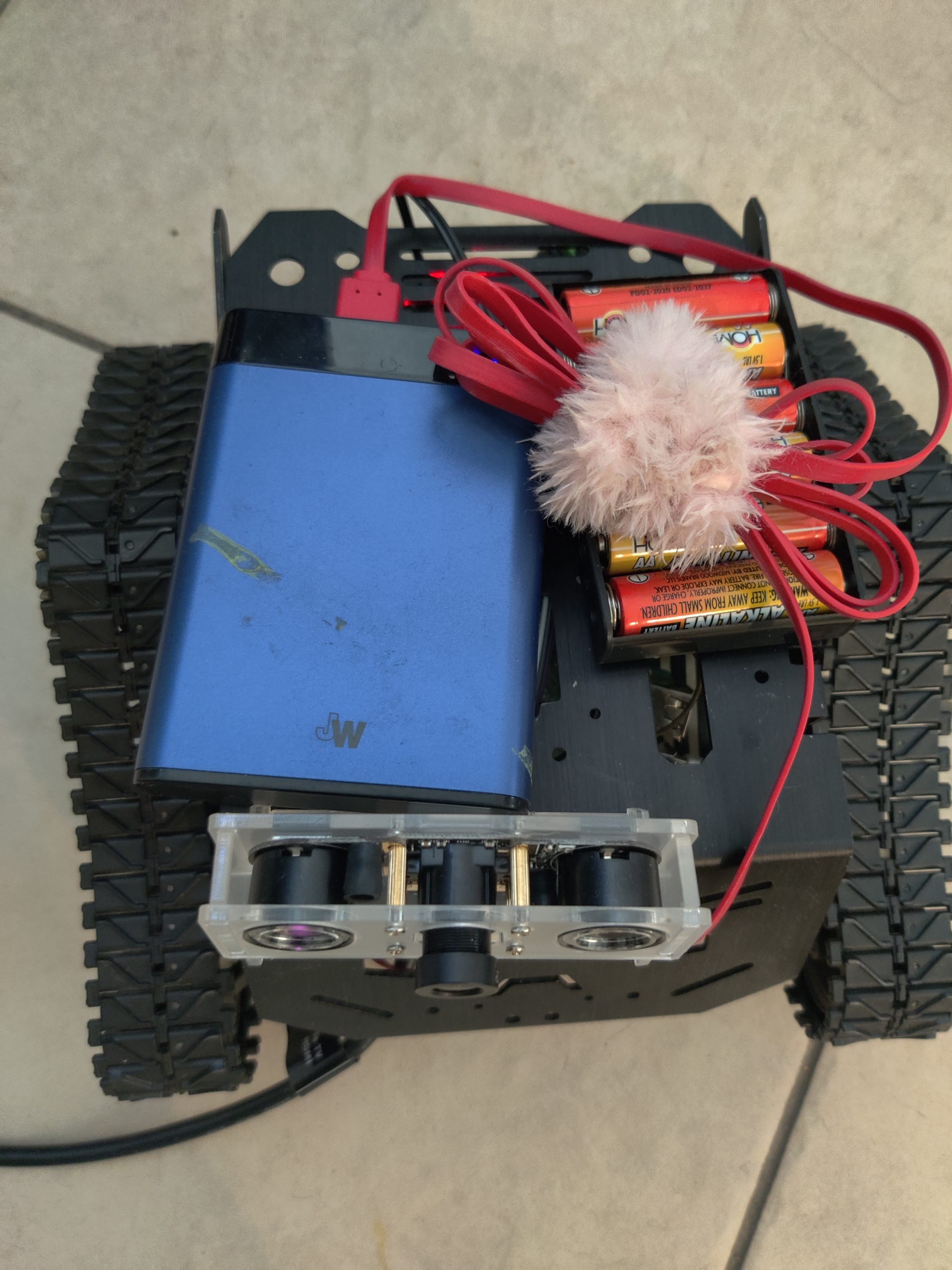
Building the kit is fairly straight forward. Once the motors and tracks are mounted in place the Raspberry Pi 3 and L298N Motor Controller fit on opposite sides of the motors comfortably. The Devastator robot kit comes with a battery holder fitting 6 AA batteries. In the Youtube series above you can see the one battery holder powers both the motors and the Pi. The project here will maintain 2 separate power sources in hopes of extending usage time. The top surface of the robot was used to store the batteries.


General Purpose Input/Output Pins (GPIO)
You can see the wires connected to the GPIO pins on the bottom right side of the Raspberry Pi. There are 40 pins total with each having its own dedicated function. See the picture below for a more detailed look.

Our Devastator Robot does not use all 40 of the GPIO pins. We have only 5 pins being used at the moment. Viewing the GPIO Graph you can see there are 3 different types of pins. There are pins for power (both 3.3 and 5v), pins for ground, and different types of GPIO pins. The pins may be used for diverse functions including reading information from sensors, providing signals to switches, or even powering a L298N Motor controller board as we do with this project.

Comparing the pin placement in our project and the graph you can see we are using the physical GPIO pins 11, 13, 15, 16, and the ground pin 6. We will use the 1st 4 pins in our code to control the motors. The first part of the code imports the Curses and GPIO libraries needed for keyboard motor control
The code
#import curses and GPIO
import curses
import RPi.GPIO as GPIO
import os #added so we can shut down ok

#set GPIO numbering mode and define output pins
GPIO.setmode(GPIO.BOARD)
GPIO.setup(11, GPIO.OUT)
GPIO.setup(13, GPIO.OUT)
GPIO.setup(15, GPIO.OUT)
GPIO.setup(16, GPIO.OUT)

#get the curses window, turn off echoing of keyboard to screen, turn on
#instant (no waiting )key response, and use special values for cursor keys
screen=curses.initscr()
curses.noecho()
curses.cbreak()
screen.keypad(True)

try:
    while True:
        char = screen.getch()
        if char ==ord('q'):
            break
        if char == ord('S'): #added for shutdown on capital s
            os.system ('sudo shutdown now') #shutdown right now
        elif char == curses.KEY_UP:
            GPIO.output(11,False)
            GPIO.output(13,True)
            GPIO.output(15, False)
            GPIO.output(16,True)
        elif char == curses.KEY_DOWN:
            GPIO.output(11,True)
            GPIO.output(13,False)
            GPIO.output(15, True)
            GPIO.output(16,False)
        elif char == curses.KEY_RIGHT:
            GPIO.output(11,True)
            GPIO.output(13,False)
            GPIO.output(15, False)
            GPIO.output(16,True)
        elif char == curses.KEY_LEFT:
            GPIO.output(11,False)
            GPIO.output(13,True)
            GPIO.output(15, True)
            GPIO.output(16,False)
        elif char == 10:
            GPIO.output(11,False)
            GPIO.output(13,False)
            GPIO.output(15, False)
            GPIO.output(16,False)

finally:
    #close down curses properly, inc turn echo back on!
    curses.nocbreak(); screen.keypad(0); curses.echo()
    curses.endwin()
    GPIO.cleanup()